By A Mystery Man Writer

Figure 1. Scheme for no rotation, counterclockwise rotation, and clockwise rotation of QRS transition zone. - "Counterclockwise and Clockwise Rotation of QRS Transitional Zone: Prospective Correlates of Change and Time‐Varying Associations With Cardiovascular Outcomes"
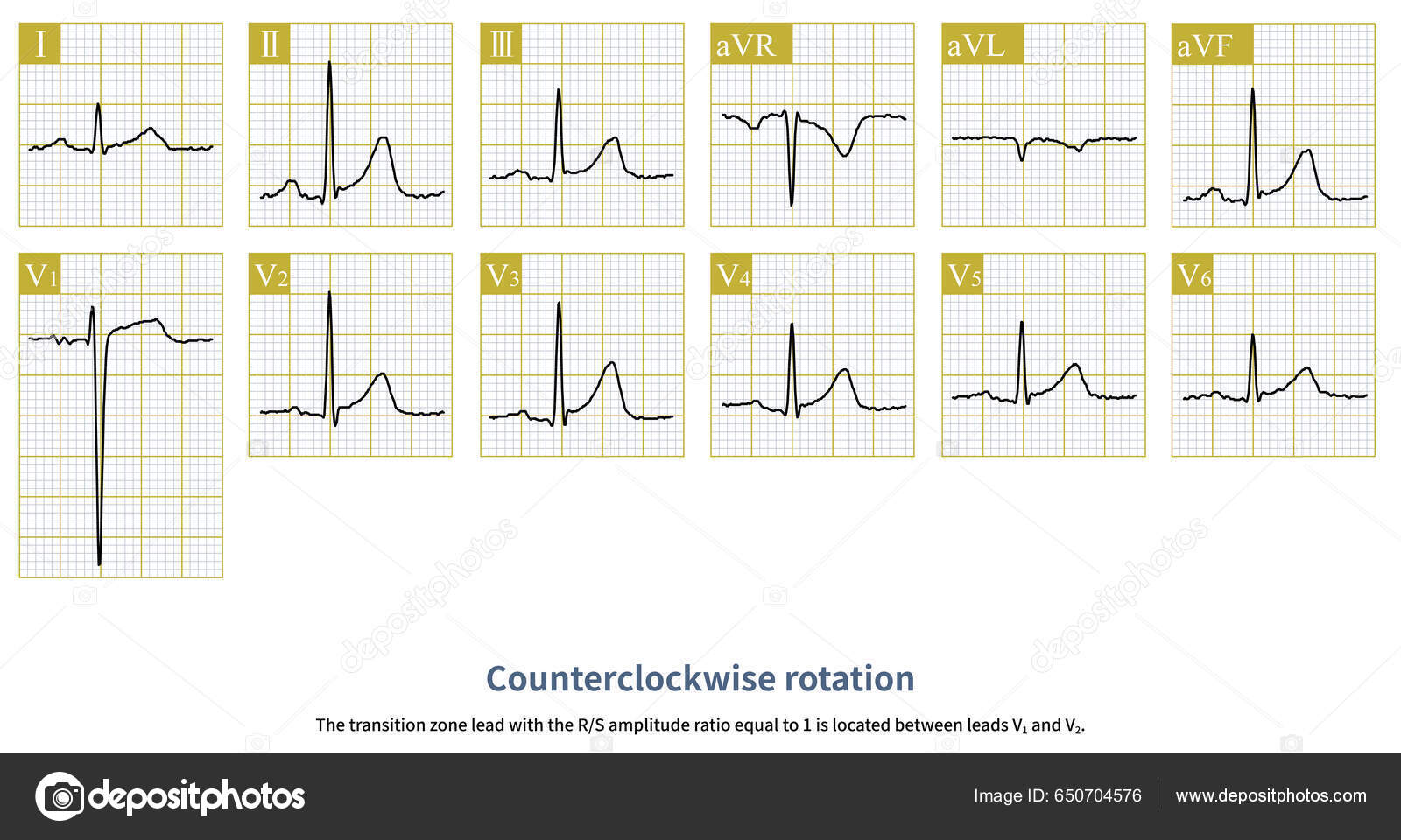
Chest Leads Amplitude Ratio Wave Wave Greater Leads Called Counterclockwise Stock Photo by ©asia11m 650704576

The Electrical Axis and Cardiac Rotation - Basic and Bedside Electrocardiography, 1st Edition (2009)

The Electrical Axis and Cardiac Rotation - Basic and Bedside Electrocardiography, 1st Edition (2009)

Twisting motion measured at 5 points of the left ventriclular free

The Electrical Axis and Cardiac Rotation - Basic and Bedside Electrocardiography, 1st Edition (2009)

Table 3 from Counterclockwise and Clockwise Rotation of QRS Transitional Zone: Prospective Correlates of Change and Time‐Varying Associations With Cardiovascular Outcomes

Vector loops and ECGs of A) counterclockwise and B) clockwise flutter

Advances of Implantation Techniques for Conduction System Pacing - ScienceDirect

Rotation of LV base and apex during the different phases of the cardiac

Graph the image of triangle ABC after a rotation of 180 degrees clockwise around the origin. Identify the vertices of the new triangle, A'B'C
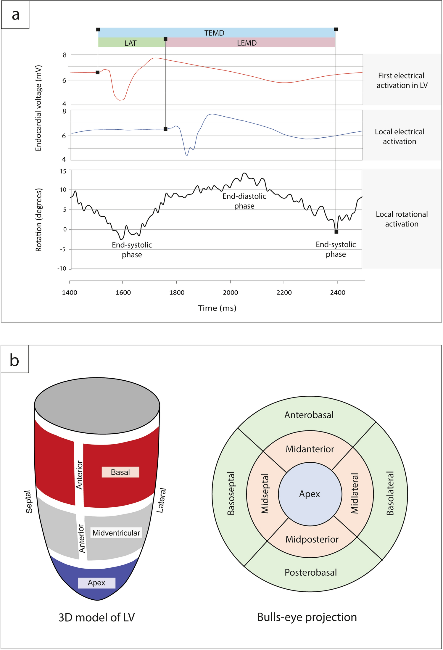
Local electromechanical alterations determine the left ventricle rotational dynamics in CRT-eligible heart failure patients
Assessment of the Rotation Motion at the Papillary Muscle Short-Axis Plane with Normal Subjects by Two-Dimensional Speckle Tracking Imaging: A Basic Clinical Study

The Electrical Axis and Cardiac Rotation - Basic and Bedside Electrocardiography, 1st Edition (2009)